
 Micro Dynamic Sensor
  Sample Preparation
  Test Accessories
  Digital Image Measurement
  Geotechnical Tests
  Rock Tests
  Coarse-grained Soil Tests
  Other Tests
  In-situ Tests
  Engineering Investigation
  Drilling Rigs
  Ocean Testing
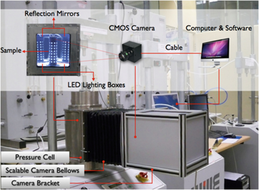
This technology represents a world-leading solution for displacement and strain measurement, meticulously designed for testing geotechnical and granular materials. Using a single camera, it enables 360° full-surface deformation measurement of specimens, successfully breaking through technical bottlenecks of traditional testing instruments in specimen deformation measurement. At present, this technology can be seamlessly integrated with various triaxial test systems, plane strain test systems and dynamic triaxial test systems.
Adopting sub-pixel corner detection, full-field surface deformation measurement, strain calculation, image stitching and error correction technologies, it solves challenges in radial deformation measurement and unsaturated soil deformation measurement, and realizes both local and full-surface deformation measurement with micron-level accuracy.
Technical Features
The only technology worldwide to truly achieve full circumferential surface measurement of geotechnical specimens with a single camera.
Non-contact measurement with zero specimen disturbance, eliminating the effects of end restraints and membrane embedment.
Simultaneous measurement of both deformation fields and displacement fields.
Synchronous measurement of axial and circumferential deformation.
Flexible selection of any cross-section or measurement location for analysis.
Supports in-depth research of layered structures, detailed characteristics and shear failure processes.
Strain measurement accuracy is at least two orders of magnitude higher than conventional methods.
Under a field of view of 165 mm (H) × 24 mm (V) and standard ambient temperature, deformation measurement accuracy achieves the micrometer (μm) grade.
Using a 5 mm × 5 mm calibration length (machining accuracy: 0.25 μm), the maximum absolute error is 0.0065 mm in the X-direction and 0.0081 mm in the Y-direction, with relative error at the μm level.
Calibrated against strain gauge readings on metallic materials, the average measurement error is 0.007%. Strain measurement accuracy reaches 10⁻⁵ for direct measurement and 10⁻⁴ for mirrored measurement.
Technical Principle
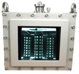
A. The specimen is placed in a cylindrical triaxial cell with a transparent tempered glass front. Two plane mirrors at a 120° included angle inside the cell capture the specimen’s rear surface images. One set of LED strip lights is fixed at both the upper and lower ends inside the cell to optimize lighting for corner detection. A high-resolution camera outside the cell captures the specimen’s front and rear images through the tempered glass.

High-resolution single camera + 120° angle mirror for full-surface image acquisition
B. The system captures and stores images of the specimen at set time intervals, and uses a sub-pixel corner detection algorithm to identify the corners of the white squares on the surface of the rubber membrane in real time.

C. The system transforms the corner points of the left, middle and right parts of the image into a planar coordinate system with the same object distance, stitches the flattened planar images of the three cylindrical surfaces into a complete unfolded surface map of the specimen, and finds the stitching position with the minimum comprehensive error through an optimization algorithm.

D. The system calculates the 3D spatial coordinates of the specimen's corner points from their coordinates on the 2D imaging plane, and computes the specimen's strain based on the coordinates of each corner point at different times.

Research Case


Recording of Shear Band Propagation Process

Calculation Results of Shear Band Width, Shear Failure Angle and Shear Band Length
Constitutive Relationship Study
By adopting the digital image measurement method for the full-surface deformation of soil samples, this study investigates the stress-strain properties and constitutive relationship of soil samples under small strains and prior to failure, based on local deformation measurements. Through low-stress cyclic loading-unloading tests, it is observed that a steady-state stress-strain hysteresis curve free of irrecoverable deformation can be achieved after several loading-unloading cycles. On this basis, elastic strain and plastic strain can be effectively separated, thereby establishing a new stress-strain constitutive relationship for soils and porous media.

Axial Strain-Deviatoric Stress Relationship Curve Relationship between Cycle Number and Cumulative Strain Increment
By selecting local points inside and outside the shear band and observing their axial strain-deviatoric stress relationship curves, it can be concluded that once the soil undergoes shear failure and forms a shear band, the strain of nodes outside the band ceases to increase, while the "strain" of nodes inside the band continues to rise.


 Customer Service QQ